Last updated on December 24th, 2023
Are you facing challenges to navigate the complexities of device communication amidst the rapid evolution of microcontrollers? The search for efficient and adaptable communication protocols within embedded systems can seem overwhelming. But fret not, as our comprehensive guide is tailored to dive deep into the world of SPI with Arduino, directly addressing these challenges.
For many enthusiasts and developers, establishing seamless communication between microcontroller-driven devices poses significant hurdles. Our guide is designed precisely to overcome these obstacles by demystifying the intricacies of SPI. From unraveling its theoretical foundations to furnishing practical examples and insights into Arduino board compatibility, we present an exploration of SPI communication geared towards actionable solutions

Introduction to SPI
The Serial Peripheral Interface, or SPI, serves as the main full-duplex, synchronous communication method. It is widely used to share data between microcontrollers, sensors, displays, and peripherals. SPI connects a master and multiple slave devices, transferring data sequentially.
SPI Protocol and Interface
In the realm of SPI, there are four key indicators to look out for:
- MISO (Master in Slave Out): Data travels from slave to master.
- MOSI (Master Out Slave In): Data flows from master to slave.
- SCK (Serial Clock): The master generates this necessary clock signal.
- SS/CS (Slave Select/Chip Select): It isolates the desired slave device in scenarios with multiple SPI-sharing devices.
Additionally, the SPI interface operates in different modes, characterized by clock phase and polarity.
Understanding SPI Modes and Their Significance
In the context of SPI communication, SPI mode selection (CPOL and CPHA) is of great importance, as it controls when data is captured and which clock signal is transmitted. Is. Let’s dive deeper into each mode:
- SPI Mode 0 (CPOL=0, CPHA=0):
- The clock stays low during idle.
- Data is captured on the leading (rising) edge.
- SPI Mode 1 (CPOL=0, CPHA=1):
- The clock stays low during idle.
- Data is captured on the trailing (falling) edge.
- SPI Mode 2 (CPOL=1, CPHA=0):
- The watch rests more during idle.
- Data is captured on the leading (rising) edge.
- SPI Mode 3 (CPOL=1, CPHA=1):
- The watch rests more during idle.
- Data is captured on the trailing (falling) edge.
Choosing the appropriate SPI mode depends on the unique demands of your project. For example, when connecting to a specific sensor or display, refer to the device data sheet for the recommended SPI mode. A wrong choice can lead to communication errors.
Arduino SPI Library
When utilizing the capabilities of SPI with Arduino, there is no need to go into complex low-level coding. Arduino offers a user-friendly library for your convenience. Just initialize the SPI library in your Arduino sketch with this line:
#include <SPI.h>SPI Pins on Arduino Boards
Arduino Uno, Mega, and Nano are popular boards that support SPI communication. The pins for SPI communication on these boards are:
Arduino Uno SPI Pins:
- MISO: Digital Pin 12
- MOSI: Digital Pin 11
- SCK: Digital Pin 13
- SS/CS: Digital Pin 10
Arduino Mega SPI Pins:
- MISO: Digital Pin 50
- MOSI: Digital Pin 51
- SCK: Digital Pin 52
- SS/CS: Digital Pin 53
Arduino Nano SPI Pins:
- MISO: Digital Pin 12
- MOSI: Digital Pin 11
- SCK: Digital Pin 13
- SS/CS: Digital Pin 10
Arduino to Arduino SPI Communication
Connecting two Arduino boards together using SPI communication is a powerful way to share data. One Arduino acts as the master, the other as the slave. Here is a basic approach to establishing this relationship for Arduino Mega:
Master Arduino Sketch:
#include <SPI.h>
#define SS_PIN 53 // Specify the Slave Select (SS) pin number
char send_Data[] = "ucbeginner"; // Data to send
void setup() {
// Initialize SPI communication
SPI.begin();
pinMode(SS_PIN, OUTPUT);
digitalWrite(SS_PIN, HIGH);
}
void loop() {
SPI.beginTransaction(SPISettings(1000000, MSBFIRST, SPI_MODE0)); // Start the SPI transaction
digitalWrite(SS_PIN, LOW);
for(int i=0; i< sizeof(send_Data); i++)
{SPI.transfer(send_Data[i]); }// Send the data byte
digitalWrite(SS_PIN, HIGH);
SPI.endTransaction(); // End the SPI transaction
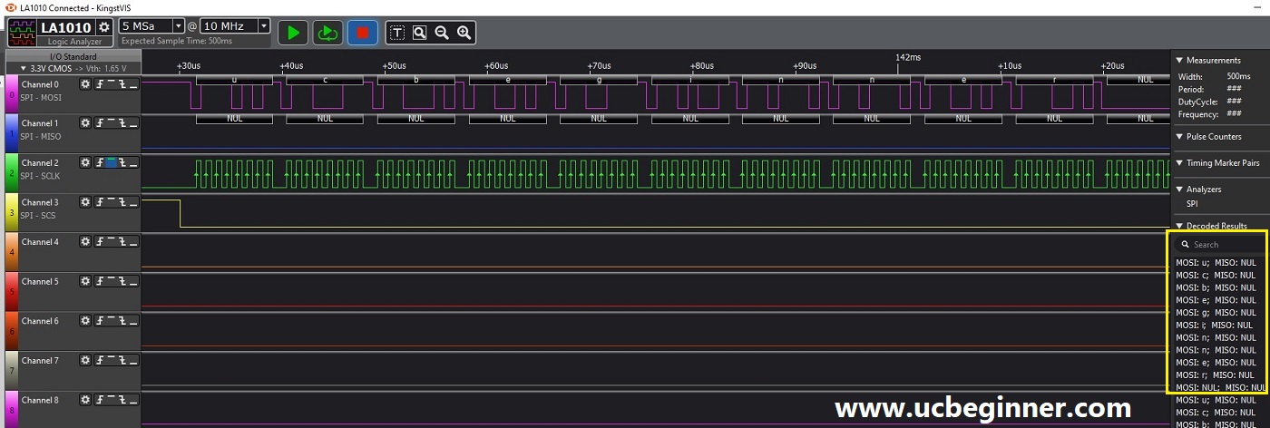
}What you see on the logic analyzer screen for SPI.
To see on your PC/Laptop please download the Logic analyzer data (.kvdat) file.
Slave Arduino Sketch:
#include <SPI.h>
byte Data;
byte send_data_to_master = "slave";
void setup() {
  SPI.begin();
  attachInterrupt(digitalPinToInterrupt(10), on_data, FALLING); // Set up an interrupt on the SS/CS pin
  Data = 0;
  Serial.begin(9600);
}
void loop() {
  SPI.transfer(send_data_to_master);
}
void on_data() {
  Data = SPI.transfer(0); // Receive data from the master
  Serial.print("Received data is = ");
  Serial.println(Data, HEX);
}
Arduino SPI Examples
Example 2: SPI Communication with an SPI-Compatible Sensor
Let’s connect an SPI-compatible sensor (for example, an SPI-enabled temperature sensor) to the Arduino Mega and read the temperature data.
#include <SPI.h>
int CS = 10;
void setup() {
  SPI.begin();
  Serial.begin(9600);
  pinMode(CS, OUTPUT);
  digitalWrite(CS, HIGH);
}
void loop() {
  digitalWrite(CS, LOW);
  int Data = SPI.transfer16(0x0000); // Read 16-bit temperature data
  digitalWrite(CS, HIGH);
  float temp = Data * 0.25;
  Serial.print("Temperature = ");
  Serial.print(temp);
  Serial.println(" °C");
  delay(1000);
}
Example 3: SPI Communication with an SD Card Module
Let’s connect an SD card module to the Arduino Due and read and write data to/from the SD card.
#include <SPI.h>
#include <SD.h>
int CS = 4;
void setup() {
  Serial.begin(9600);
  if (!SD.begin(CS)) {
    Serial.println("SD card initialization failed.");
    return;
  }
  Serial.println("SD card initialized.");
}
void loop() {
  File dataFile = SD.open("data.txt", FILE_WRITE);
  if (dataFile) {
    dataFile.println("Hello, world!");
    dataFile.close();
    Serial.println("Data written to SD card.");
  } else {
    Serial.println("Error opening data.txt.");
  }
  delay(1000);
  File Read_file_data = SD.open("data.txt");
  if (Read_file_data) {
    while (Read_file_data.available()) {
      Serial.write(Read_file_data.read());
    }
    Read_file_data.close();
  } else {
    Serial.println("Error!");
  }
 delay(1000);
}
Low level/Register Level SPI code
Benefits of Low-Level SPI Code
- Performance: Low-level SPI code provides precise control over SPI hardware, increasing performance. Tailor your code to meet the precise timing and data transfer needs of your unique application.
- Resource efficiency: Direct management of registers can reduce code memory usage, which is a boon for resource-constrained setups.
- Real-time accuracy: Low-level SPI code is better in scenarios that require real-time data transfer and synchronization with other program components.
- Educational value: Writing low-level code deepens your understanding of microcontroller SPI hardware, which fosters expertise in embedded systems development.
- Portability: Low-level code provides easy adaptation to different microcontroller platforms, with less dependency on specific libraries, making transitions easier.
- Customization: Enjoy complete control over data framing, transfer, and synchronization in your SPI communication. Ideal for complex projects with varying requirements.
Although low-level SPI code brings many advantages, it demands an in-depth understanding of microcontroller hardware. For quick prototyping and ease of use, Arduino’s built-in libraries may be more suitable. Choosing between low-level and high-level SPI coding depends on the needs of your project and your skill level.
Low-Level SPI Code for Arduino Uno
#define SPI_DDR DDRB
#define CS      PINB2
#define MOSI    PINB3
#define MISO    PINB4
#define SCK     PINB5
void SPI_masterTransmitByte(uint8_t data);
void SPI_init();
char t_data[] = "ucbeginner";
void setup() {
  SPI_init();
  }
void loop() {
    // transmit byte to slave
    for(int i=0; i<sizeof(t_data);i++)
       { SPI_masterTransmitByte(t_data[i]);  }
        _delay_us(500);
 }
void SPI_init()
 {
  // set CS, MOSI and SCK to output
  SPI_DDR |= (1 << CS) | (1 << MOSI) | (1 << SCK);
  // enable SPI, set as master, and clock to fosc/128
  SPCR = (1 << SPE) | (1 << MSTR) | (1 << SPR1) | (1 << SPR0);
 }
void SPI_masterTransmitByte(uint8_t data)
 {
  // load data into register
  SPDR = data;
  // Wait for transmission complete
  while(!(SPSR & (1 << SPIF)));
  }
SPI Output on Logic Analyzer
To see on your PC/Laptop please download the Logic analyzer data (.kvdat) file.
Common SPI Devices Interfacing with Arduino
- SPI Sensor:
- Accelerometers and gyroscopes: Devices like the MPU-6050 and ADXL345 find applications in motion sensing and orientation tracking for robotics and IoT projects.
- Temperature Sensors: The MAX31855 and similar SPI-connected sensors offer accurate temperature measurements in a variety of applications.
- SPI display:
- TFT and OLED displays: ILI9341 and SSD1306, among others, bring graphical interface and visual feedback to Arduino projects.
- SPI Memory Devices:
- EEPROM: Serial EEPROM chips such as the 25LC256 serve as a non-volatile data storage solution.
- Flash memory: W25Q series SPI flash chips are ideal for storing large data sets or program code.
- SPI Communication Modules:
- Wireless Transceivers: Modules like the nRF24L01 enable wireless communication in applications such as remote control and sensor networks.
- Ethernet modules: ENC28J60 and similar modules empower Arduino boards to connect to Ethernet networks, expanding their network capabilities.
- SPI Audio Devices:
- Audio Codecs: Devices such as the MAX98357A facilitate microphone and speaker interfacing, enabling audio playback and recording in various projects.
- SPI Real-Time Clocks (RTCs):
- RTC modules such as DS3231: These ensure accurate timekeeping in Arduino projects, often used in data logging and scheduling applications.
- SPI Motor Controllers:
- Motor driver modules such as the L298N and L293D: Play an important role in controlling motors and robotic actuators for a wide range of applications.
- SPI Data Converters:
- Devices such as the MCP3008: They perform analog-to-digital conversion, extending the Arduino’s ability to interface with analog sensors.
- SPI Expansion Boards:
- Boards such as the MCP23S17: These provide additional GPIO pins, meeting the needs of projects that require more digital inputs and outputs.
Benefits of SPI Devices with Arduino
- Versatility: Arduino’s seamless integration with a multitude of SPI devices promotes project diversity, spanning IoT innovations, robotics ventures, and data collection systems.
- Performance: SPI’s reputation for high-speed data transfer makes it indispensable for scenarios that demand rapid data exchange.
- Data Accuracy: An array of SPI devices, from sensors to data converters, provides accurate measurements and complex data processing.
- Modularity: SPI device modularity allows straightforward expansion of Arduino capabilities while preserving the basic functionality of the board.
- Customization: SPI devices are suitable for project-specific configurations. Customize communication settings, data formats, and other parameters to your specific project needs.
- Expandability: The market is flooded with SPI devices, offering Arduino users a wide spectrum of options to expand project capabilities.
Conclusion
Finally, our exploration of SPI communication alongside the Arduino has unveiled a realm full of potential for enthusiasts in the microcontroller and embedded systems domain. We’ve stepped from the basics of SPI methods to the user-friendly realm of the Arduino SPI library, providing a comprehensive roadmap. By understanding the intricacies of SPI pins on Arduino boards, stepping into Arduino-to-Arduino SPI communication, and mastering the invaluable skills involved in low-level SPI code, we equip readers with the ability to The abundance of SPI devices compatible with Arduino projects, embedded sensors, displays, memory components, communication modules, and more, offers endless avenues for creativity. Regardless of your experience level, whether a novice or a seasoned developer, SPI with Arduino opens the door to breakthrough solutions and problem-solving in the ever-evolving universe of microcontrollers and embedded systems.