Are you struggling to make devices talk to each other smoothly in embedded systems? Finding a good way to move data between them among all the options out there can feel overwhelming. That’s where the I2C protocol steps in—it’s like a bright solution in a world of communication challenges.
This guide is here to help you understand the problems embedded system developers often face. And guess what? The I2C protocol is the hero we’ll explore to solve those problems. We’ll dive into how it works, simplifying the tough bits and showing you everything from the basics to how it’s used. Come along on this journey to see why the I2C protocol is a game-changer in integrated circuits. It’s the answer to making communication in embedded systems dependable and smooth.

Understanding the Basic Concepts of the I2C Protocol
What is I2C?
I2C, an abbreviation of Inter-Integrated Circuit, serves as a serial communication protocol crafted to facilitate interaction among integrated circuits, enabling numerous devices to communicate through a common bus. Originating from Philips Semiconductor, now known as NXP Semiconductors, this protocol is recognized for its straightforwardness and effectiveness in transmitting data.
How Does the I2C Protocol Work?
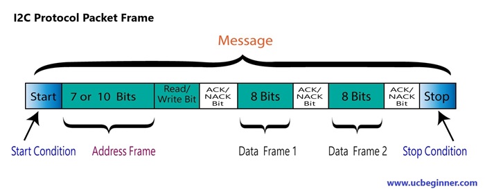
I2C functions through message-based data transfer, breaking messages into data frames. Each message consists of an address frame holding the binary slave address and one or more data frames with the transmitted data. This process involves start and stop conditions, read/write bits, and acknowledgment (ACK)/non-acknowledgment (NACK) bits interspersed between data frames:

- Start Condition: The SDA line undergoes a transition from a high to a low voltage level before the SCL line shifts from high to low.
- Stop Condition: The SDA line switches from a low to a high voltage level after the SCL line transitions from low to high.
- Address Frame: A distinctive 7 or 10-bit sequence unique to each slave, enabling communication with the master.
- Read/Write Bit: A solitary bit specifying whether the master sends data to the slave (low voltage level) or requests data from it (high voltage level).
- ACK/NACK Bit: Following each frame in a message is an acknowledgment or non-acknowledgment bit. An ACK bit is transmitted back to the sender if an address or data frame was received successfully by the receiving device.
Key Components and Functionality
I2C Bus
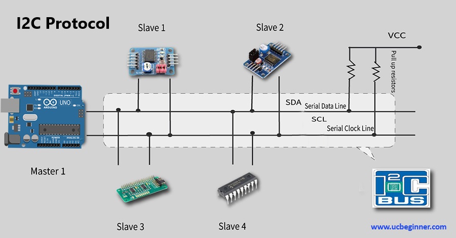
The I2C bus serves as the physical link through which information is exchanged among devices. It consists of two essential lines: the Serial Data Line (SDA) responsible for conveying the data and the Serial Clock Line (SCL) that regulates the timing of data transfer.
I2C Protocol Analyzer
To streamline the debugging and analysis of I2C communication, I2C protocol analyzers are essential. These instruments empower developers to observe and scrutinize the exchanged data among devices, assisting in pinpointing and resolving communication glitches.
I2C Transmission and Data Frame
In the I2C protocol, data transmission takes place within frames, comprising an address byte followed by data bytes. This methodical method guarantees dependable and orderly data interchange among devices.
Applications and Implementations
I2C Protocol in Embedded Systems
The I2C protocol is widely used in embedded systems, spanning from tiny sensors and EEPROMs to intricate setups such as microcontrollers and FPGAs. Its adaptability and effectiveness render it a top pick for a range of embedded uses.
I2C Communication in ESP32 and FPGA
The ESP32 utilizes the I2C protocol to facilitate communication between devices, ensuring smooth connectivity in IoT applications. Likewise, FPGAs rely on I2C for configuring and communicating with peripheral devices, drawn to its adaptable and dependable nature.
I2C Multi-Slave Configuration and Device Addressing
The I2C protocol stands out for its ability to accommodate numerous slave devices on a single bus. Each individual slave device possesses a distinct address, enabling the master device to communicate with designated slaves while others remain dormant.
Arduino Code Examples
Example 1: Master-Slave Communication
Master Code (Arduino Uno): This code acts as the master device, sending data to a slave device.
#include <Wire.h>

void setup() {
  Wire.begin(); // Initialize I2C communication as Master
  Serial.begin(9600); // Initialize Serial Monitor
}

void loop() {
  Wire.beginTransmission(8); // Address of the Slave (change accordingly)
  Wire.write("www.ucbeginne.com!"); // Data to be sent
  Wire.endTransmission(); // Stop transmitting

  delay(1000); // Wait for a second before sending the next data
}
Slave Code (Arduino Uno): This code configures an Arduino as the slave device, receiving data from the master.
#include <Wire.h>

void setup() {
  Wire.begin(8); // Initialize I2C communication as Slave with address 8
  Wire.onReceive(receiveEvent); // Function to run when data received
  Serial.begin(9600); // Initialize Serial Monitor
}

void receiveEvent(int bytes) {
  while (Wire.available()) { // While there is data to receive
    char c = Wire.read(); // Read the incoming byte
    Serial.print(c); // Print the received data on Serial Monitor
  }
  Serial.println(); // Print a new line
}

void loop() {
  delay(100); // Add a small delay in the loop
}
Example 2: Using I2C for Sensor Communication
Master Code (Arduino Uno): This code reads data from a sensor (e.g., an MPU6050 accelerometer/gyroscope) connected via I2C.
#include <Wire.h>

const int MPU_addr = 0x68; // MPU6050 I2C address

void setup() {
  Wire.begin(); // Initialize I2C communication as Master
  Serial.begin(9600); // Initialize Serial Monitor
  Wire.beginTransmission(MPU_addr); // Start communication with MPU6050
  Wire.write(0x6B); // PWR_MGMT_1 register
  Wire.write(0); // Wake up MPU6050
  Wire.endTransmission(true); // Stop transmitting
}

void loop() {
  Wire.beginTransmission(MPU_addr); // Start communication with MPU6050
  Wire.write(0x3B); // Start with register 0x3B (ACCEL_XOUT_H)
  Wire.endTransmission(false); // Restart transmission, keep connection active

  Wire.requestFrom(MPU_addr, 14, true); // Request 14 bytes from MPU6050

  while (Wire.available() < 14); // Wait until all the bytes are received

  int16_t AcX = Wire.read() << 8 | Wire.read(); // Read accelerometer data
  int16_t AcY = Wire.read() << 8 | Wire.read();
  int16_t AcZ = Wire.read() << 8 | Wire.read();

  int16_t GyX = Wire.read() << 8 | Wire.read(); // Read gyroscope data
  int16_t GyY = Wire.read() << 8 | Wire.read();
  int16_t GyZ = Wire.read() << 8 | Wire.read();

  Serial.print("Accelerometer: ");
  Serial.print("X = "); Serial.print(AcX);
  Serial.print(" | Y = "); Serial.print(AcY);
  Serial.print(" | Z = "); Serial.println(AcZ);

  Serial.print("Gyroscope: ");
  Serial.print("X = "); Serial.print(GyX);
  Serial.print(" | Y = "); Serial.print(GyY);
  Serial.print(" | Z = "); Serial.println(GyZ);

  delay(1000); // Wait for a second before reading again
}
Advantages and Challenges
Advantages of I2C Protocol
- Facilitating efficient data transfer among multiple devices, it boosts effectiveness.
- Its versatility lies in supporting a diverse array of applications within embedded systems.
- Through multi-slave configuration, several devices can concurrently access and share the bus.
Challenges and Considerations
- Clock Stretching: can introduce delays in the clock signal, impacting timing in certain devices.
- Limited Speed: The limited clock frequency of I2C might make it unsuitable for high-speed applications.
I2C’s Range Constraints:
The I2C protocol functions over limited distances primarily because it relies on open-drain drivers within its bus structure. These drivers employ pull-up resistors to return the bus to its idle state, restricting the distance due to capacitance and wire resistance.
Generally, the maximum span between two I2C devices remains relatively short, typically within a few meters. The effective distance without compromising signal integrity hinges on various factors like wire quality, pull-up resistor specifications, and the presence of electrical interference in the surrounding environment.
Significance of I2C Protocol
The I2C (Inter-Integrated Circuit) protocol holds immense importance within embedded systems and integrated circuits due to several key reasons:
- Streamlined Communication: It offers a direct and efficient way for multiple devices to communicate over a shared bus, ensuring smooth data exchange among interconnected elements.
- Adaptability: I2C boasts versatility by accommodating a broad spectrum of devices, ranging from sensors and memory chips to intricate integrated circuits. This fosters compatibility and easy integration across diverse applications.
- Multi-Device Connectivity: Its architecture enables numerous master and slave devices to communicate on a single bus, facilitating complex systems without the need for individual communication lines per device.
- Simplicity: The protocol’s simplicity lies in its two-wire design (SCL and SDA), making implementation and troubleshooting relatively straightforward. This simplicity reduces development intricacies and time.
- Debugging and Analysis Tools: Developers benefit from I2C protocol analyzers, aiding in effective debugging and communication analysis between devices, which significantly assists troubleshooting and development.
Conclusion
The I2C protocol is pivotal for efficient communication in embedded systems, prized for its simplicity and versatility. Essential for developers handling integrated circuits, it shapes seamless communication in complex applications, continually evolving to define the landscape of embedded systems. Its enduring significance fuels ongoing innovation, ensuring effective inter-device communication and paving the way for future technological advancements.
I2C Protocol Interview Questions:
1. What is I2C?
I2C stands for Inter-Integrated Circuit, a serial communication protocol for inter-device communication.
2. How does I2C work?
It utilizes a master-slave architecture where a master device initiates communication and controls the data flow.
3. What are the key lines in I2C?
SDA (Serial Data Line) carries data, while SCL (Serial Clock Line) regulates the timing of data transmission.
4. What is the maximum speed of I2C?
Standard mode operates at 100 kbit/s, while fast mode reaches speeds up to 400 kbit/s. High-speed mode can reach up to 3.4 Mbit/s.
5. How does I2C differ from SPI and UART?
6. What is 10-bit addressing in I2C?
It extends the address space, allowing a larger number of devices to be connected on the bus by using a 10-bit device address.
