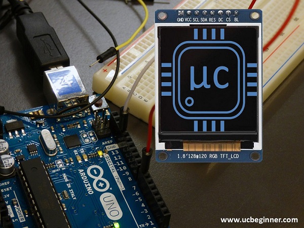
Struggling to bring vibrant displays to your Arduino projects? The integration of the ST7735 TFT display might be the breakthrough you need. This common challenge for both beginners and experts in the Arduino community is finding a reliable and versatile display module that truly enhances their projects. Whether it’s understanding the technical specifications or implementing the display with the right libraries, the journey can be daunting.
Fear not, as our comprehensive guide is the solution you’ve been searching for. Dive into the animated world of the ST7735 Arduino Display with us, where we’ll unravel the mysteries of its datasheet, explore the vast functionalities of the ST7735 library, and showcase an enlightening Arduino example. From detailed walkthroughs on using the Adafruit ST7735 library functions to configuring the 1.44 SPI 128×128 and the 1.8 TFT display module with the ST7735 controller for ESP32 and AVR platforms, this tutorial is your gateway to mastering this adaptable display, ensuring your Arduino projects shine brighter than ever.

Introduction
The ST7735 TFT display, often referred to as the ST7735r, is a 1.8-inch screen with a resolution of 128×160 pixels. What sets it apart is its ability to display a wide spectrum of colors, with an impressive range of colors. Includes full 18-bit color support. 262,144 different shades. This display uses the SPI communication protocol, making it compatible with a variety of microcontrollers, while requiring only four I/O pins. Additionally, it comes with a convenient microSD card slot, allowing for easy loading and presentation of color bitmaps.
Let’s review the key features of the ST7735 Arduino Display:
- Includes a 1.8 inch diagonal LCD TFT screen.
- It provides support for a resolution of 128×160 pixels and displays 18-bit color (equivalent to 262,144 colors).
- The device is equipped with a digital interface that supports 4 or 5 wire SPI communication.
- There is a built-in microSD card slot for storing bitmaps.
- It is compatible with both 3.3V and 5V logic levels.
- Backlight can be dimmed using PWM and includes two white LEDs.
- For easy breadboarding, it comes with a handy 1×10 header.
- There are four 0.9 inch mounting holes for secure installation.
- The overall dimensions of the device are 1.35 inches x 2.2 inches x 0.25 inches.
- The main purpose of this tutorial is to demonstrate the capabilities of the ST7735 TFT display for images, text, and even basic animation.
ST7735 TFT Display Description
TFT LCD technology, which stands for Thin-Film-Transistor Liquid Crystal Display, improves image characteristics such as resolution and contrast. This guide will focus on the process of connecting a 1.44 inch TFT color display employing the ST7735 driver. This screen contains 128×128 color pixels, allowing for a dynamic 16-bit color presentation.
ST7735R
A specific ST7735 TFT display controller variant is often used in screens that incorporate the ST7735 chip.
ST7735 LCD datasheet
The manufacturer (or supplier) of the ST7735 TFT LCD display offers a complete set of documents called the ST7735 LCD datasheet and the datasheet for the display driver chip.
ST7735 sd card
The ST7735 TFT display features an SD card slot that simplifies the process of loading images and data, resulting in improved visual performance.
ST7735 initialization
Setting up the ST7735 TFT display to work with Arduino or microcontrollers is an essential configuration step.
ST7735 fonts
Tweak the text style, size, and visual presentation of your projects for an aesthetically pleasing display on the ST7735 TFT screen.
ST7735 backlight control
Modify backlight brightness to get the best visibility for your display and enhance visual effects.
adafruit_st7735
Adafruit has created a library specifically tailored for easy interaction between Arduino and microcontrollers and the ST7735 TFT display.
Using the TFT ST7735 Display with Arduino
In the world of microcontrollers and electronic systems, various display devices act as interfaces for users. While basic displays such as LEDs and 7-segment displays are commonly used, TFT color displays add a new dimension by allowing you to add color images and graphics to your projects.
Required Components
Before we begin our exploration, let’s gather the essential components for this tutorial:
- ST7735 Color TFT display
- Arduino Uno (or a compatible board)
- Small breadboard
- Wires for connections
You can easily acquire these components through the provided links or from your preferred electronics supplier.
Schematics
Setting up the ST7735 display with your Arduino is a simple procedure, requiring only a few connections. The display operates under the guidance of the ST7735/ST7735S/ST7735B microchip driver, which acts as a link between the display panel and the microcontroller. These displays are widely loved in the Arduino community for their ease of use and affordability, resulting in a variety of breakout board options. See Breakout Schematic.
Display Parameters
ST7735 displays come in various sizes and configurations, such as:
- 0.96″ (80×160 pixels)
- 1.44″ (128×128 pixels)
- 1.8″ (128×160 pixels)
They also provide compatibility with different color modes, such as 16-bit ‘high color’ (equivalent to 65,536 colors) and 18-bit (equivalent to 262,144 colors). They offer communication interfaces, including SPI and parallel MCUs.” with options for interfaces. 8-bit, 9-bit, 16-bit and 18-bit configurations.
To facilitate working with ST7735 displays, the xod-dev/st7735-display library provides quick start nodes for various display types, ensuring compatibility.
Connecting the TFT Display to Arduino
Although there are different pin configurations for the ST7735 display, the necessary pins for the connection remain constant. For the type of display we are using, follow these connections to your Arduino board:
- SCK to digital pin 13
- Digital pin 11 from SDA
- DC to digital pin 9
- Reset to digital pin 8.
- Digital pin 10 from CS
- GND to Arduino GND
- VCC to Arduino 3.3V
The Circuit
Installing Libraries
Step 1: Launch the Arduino IDE
Start by opening the Arduino Integrated Development Environment (IDE) on your computer. If you haven’t already installed the IDE, you can get it from the official Arduino website.
Step 2: Access the “Manage Libraries” feature
Within the Arduino IDE, go to the “Sketch” menu at the top of the window. From the drop-down menu that appears, select “Add Library” and then select “Manage Libraries…” as shown below:
Step 3: Library Manager
This process will bring up the Library Manager window, allowing you to find and install libraries. In the upper right corner, you will find a search bar.
Step 4: Find the Library
In the search bar, enter the name of the library you want to install. For example, if you want to install “Adafruit GFX Library”, type “Adafruit GFX” in the search bar.
Step 5: Install the Library
After entering the library name, you will be presented with a list of matching libraries below. Locate the desired library and click the “Install” button next to it.
Step 6: Library Installation
The IDE will then proceed to download and install the selected library. You can monitor the progress of the installation through the progress bar at the bottom of the Library Manager window.
Step 7: Library Installed
Once the installation is complete, you’ll see a message confirming that the library has been installed. You can now close the Library Manager window.
Step 8: Using the Library
To use a library that you have installed in your Arduino sketch, you usually add it to the beginning of your code. For example, if you are using the Adafruit GFX library, you would add it as follows:
#include <Adafruit_GFX.h>
After doing this, you are all set to use the functions and features provided by the library in your Arduino undertakings.
that’s it! You have successfully integrated a library into the Arduino IDE. You can follow these steps for any additional libraries you need for your projects, streamlining your access to and use of a wide variety of pre-written code and functionality within your Arduino sketches.
Quick Start Example
To get started with the ST7735 TFT display, you can follow these steps:
- Initialize the display using the appropriate Quick Start node for your display type (eg, st7735-128×160-b, st7735-128×160-g, etc.).
- Rotate the screen if needed for your project.
- Present your desired look including images, text, and animations.
This quick-start example simplifies the process of setting up and using your ST7735 display with Arduino.
Basic Commands
Most TFT libraries provide a set of essential commands for controlling the display, including:
tft.fillScreen(); //to change the screen's color.
tft.setCursor(x, y); //for setting the cursor position.
tft.setTextColor(t); //to set text color.
tft.setTextColor(t, b); //to set text and background colors.
tft.setTextSize(); //to adjust text size (typically from 1 to 5).
tft.setRotation(); //to rotate the screen (0, 90, 180, or 270 degrees).
tft.print(); //to display text.
tft.println(); //to display text and move to the next line.
tft.drawFastVLine(x, y, h, t); //for drawing vertical lines.
Arduino Code
#include <Adafruit_GFX.h>
#include <Adafruit_ST7735.h>
#include <SPI.h>

// Pin definitions
#define TFT_CS    10
#define TFT_RST    8
#define TFT_DC     9

// Create an instance of the Adafruit ST7735 library
Adafruit_ST7735 tft = Adafruit_ST7735(TFT_CS, TFT_DC, TFT_RST);

void setup() {
  // Initialize the display
  tft.initR(INITR_BLACKTAB); // Use this initialization for a black tab display
  tft.fillScreen(ST7735_BLACK); // Fill the screen with black

  // Set text color and size
  tft.setTextColor(ST7735_WHITE);
  tft.setTextSize(2);

  // Display a welcome message
  tft.setCursor(10, 10);
  tft.println("Hello, ST7735!");

  // Draw a rectangle
  tft.drawRect(20, 50, 100, 60, ST7735_RED);
}

void loop() {
  // Your loop code here
}
Where to Buy
Ready to embark on your ST7735 display journey? You can find these displays and the required components from reputable suppliers through the provided links.
Conclusion
Finally, the ST7735 Arduino display opens up exciting possibilities for creating visually appealing projects. Whether you’re interested in displaying images, text, or animations, this versatile display, combined with Arduino, offers a dynamic platform for your creativity. Start experimenting with the ST7735 display and unleash your imagination today!
