
Many solar panels users facing the inconsistent power or voltage issue because of changing sunlight condition, as result there are energy wastage and reduced efficiency. There are many MPPT are available in market but they are expensive, and some of them not working well.
There is solution, we can make own MPPT system with Arduino, which can optimize the our solar panel’s performance under any suitable condition. By this step by step guide or tutorial we will learn how to create our own MPPT system with Arduino for efficient solar energy.
Introduction to MPPT and Its Importance in Solar Power
The Solar panel generate varying amount of power depending on sunlight. Maximum Power Point Tracking (MPPT), is a control technique to make use the solar panel operates at maximum efficiency by adjusting electrical operating point.
Solar panels may not always deliver maximum power, which cause energy loss, That’s why MPPT is essential in modern solar system. From MPPT solar charge controllers to MPPT solar inverters where it efficiently improve the output of solar panel.
Why MPPT is Crucial
MPPT system continuously monitor the voltage and adjust the voltage according to battery requirements or direct for appliances, and also MPPT monitor the current and adjust it. The system increase the energy conversion by up to 30% specially in changing environmental conditions.
For example, use of MPPT solar charge controllers and MPPT solar inverters allow solar panels to efficiently charge batteries or provide power to device (Home appliance etc.) without wastage of energy.
For building a DIY MPPT solar charge controller circuit board using Arduino, first we start with understanding the core algorithm and hardware components.
Components Needed for Building an MPPT of Solar with Arduino
The list of components for design and build of MPPT as follows:
- Arduino (Uno, Mega, or any variant)
- DC-DC Converter (Buck or Boost depending on your application)
- Current Sensor (like ACS712)
- Voltage Sensor (simple voltage divider or dedicated sensor)
- MOSFET or relay for switching
- Capacitors and resistors for filtering
- LCD Display (optional for monitoring)
- Solar Panel (12V or higher, depending on your system)
Choosing the Right Components
- MPPT Solar Charge Controller: It is very crucial for solar panel to deliver maximum energy to batteries or devices by adjusting the voltage and current.
- MPPT Solar Inverter: It is use to convert DC power to AC power. For example Microtek MPPT Solar Inverter and Smarten MPPT Solar Charge Controllers are reliable commercial option, but we can also built our own MPPT system using Arduino.
Now, let start the the design and programming of our own MPPT system with Arduino.
Understanding the MPPT Algorithm
Solar panel’s MPPT system operate by continuously finding the Maximum Power Pint, There are many algorithms to do this, the most common is Perturb and Observe (P&O) and Incremental Conductance.
Perturb and Observe (P&O) Algorithm
The P&O algorithm work by perturbing the operating voltage of the solar panel and observing, and analyzing the how it effect the output power. If power increase the algorithm continues in same direction and if power decrease the direction of perturbation is reversed.
This is very simple algorithm and commonly use in DIY Arduino based projects.
Building the MPPT Solar Charge Controller with Arduino
Step-by-Step Guide
1. Circuit Design
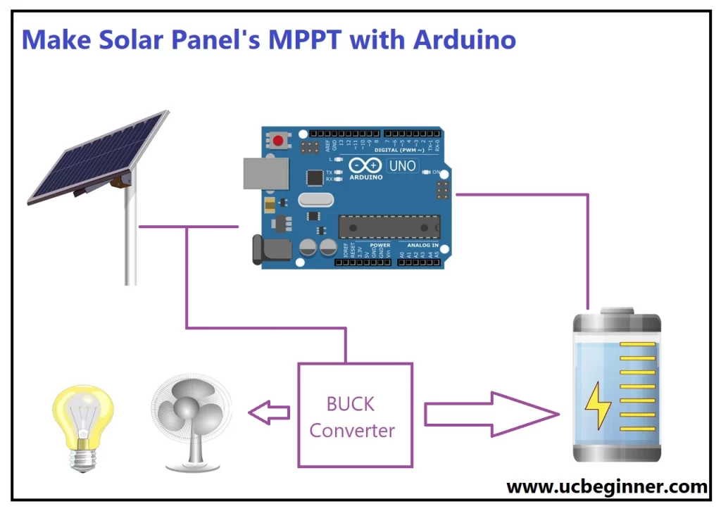
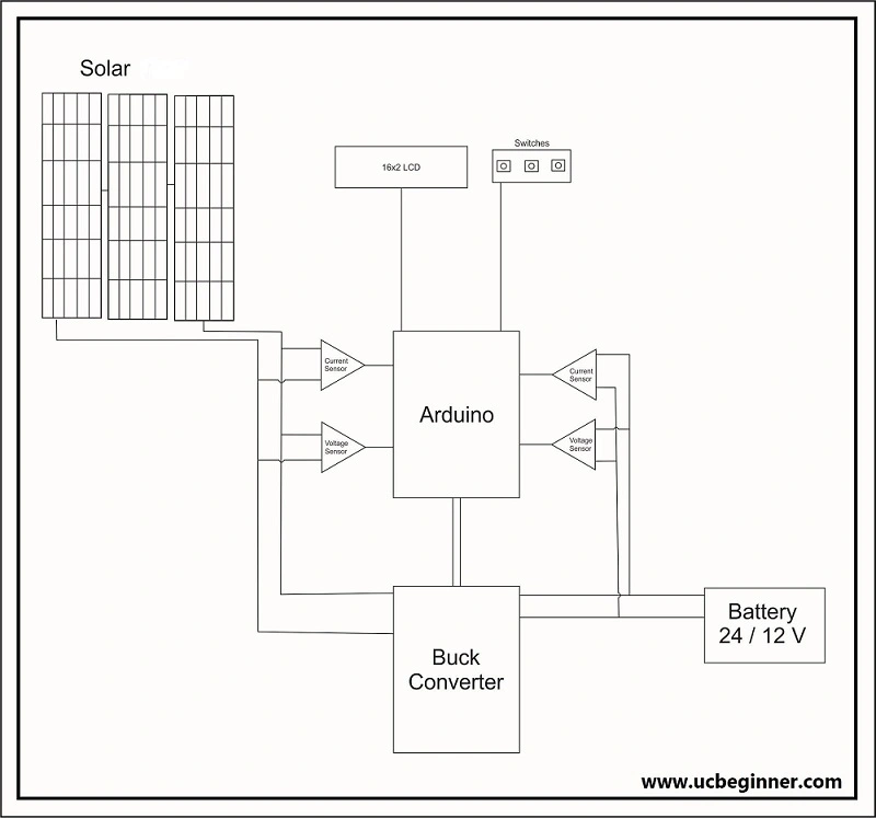
We connect solar panel to buck (DC to DC convertor) depending on our requirements. Use voltage sensor and current sensor to monitor the solar panel output voltage and current. The Arduino read the output of these sensor and adjust the duty cycle of convertor to achieve the MPPT.
We can also use voltage sensor and current sensor for battery for its monitoring.
2. Code Implementation for Arduino
Arduino code for MPPT solar charge controller using P&O algorithm:
// Pin configuration
const int voltagePin = A0;  // Pin for voltage sensor
const int currentPin = A1;  // Pin for current sensor
const int pwmPin = 9;       // Pin for controlling PWM to the DC-DC converter

// Variables for MPPT
float voltage, current, power;
float prevVoltage, prevPower;
float deltaV = 0.01;  // Small voltage change for perturbation
float dutyCycle = 0.5; // Start with 50% duty cycle

void setup() {
  pinMode(pwmPin, OUTPUT);
  Serial.begin(9600);
}

void loop() {
  // Read voltage and current from the sensors
  voltage = analogRead(voltagePin) * (5.0 / 1023.0); // Scale according to sensor
  current = analogRead(currentPin) * (5.0 / 1023.0); // Scale according to sensor
  power = voltage * current;

  // MPPT using Perturb and Observe
  if (power > prevPower) {
    if (voltage > prevVoltage) {
      dutyCycle += deltaV; // Increase duty cycle
    } else {
      dutyCycle -= deltaV; // Decrease duty cycle
    }
  } else {
    if (voltage > prevVoltage) {
      dutyCycle -= deltaV; // Decrease duty cycle
    } else {
      dutyCycle += deltaV; // Increase duty cycle
    }
  }

  // Constrain duty cycle within limits
  dutyCycle = constrain(dutyCycle, 0, 1);

  // Apply the duty cycle to the DC-DC converter
  analogWrite(pwmPin, dutyCycle * 255);

  // Update previous values
  prevVoltage = voltage;
  prevPower = power;

  // Display values (optional)
  Serial.print("Voltage: "); Serial.print(voltage);
  Serial.print(" Current: "); Serial.print(current);
  Serial.print(" Power: "); Serial.println(power);

  delay(100);  // Small delay for stability
}
3. Testing and Optimization
When circuit is completed Arduino start adjusting the duty cycle of DC-DC convertor to track Maximum power point. We can monitor voltages and current output through serial monitor of Arduino or display screen.
By adjusting the perturbation size (deltaV and sampling rate), we can optimize the performance of our MPPT charge controller. The system continue to adapt changing environment condition, ensuring the solar panel working at its peak efficiency.
Scaling the MPPT System for Different Voltage Levels
Focusing on basic 12V setup the same principles can be applied to higher voltage systems:
12V MPPT Solar Charge Controller
For small application like 12V batteries the setup we just discussed work efficiently. This is ideal solution for home solar panel system.
24V MPPT Solar Inverter
Power setup like 24V system we would use 24V MPPT solar inverter. Here MPPT system control the power flow to ensure maximum efficiency in converting solar DC to usable AC.
48V MPPT Solar Charge Controller
For large scale applications we may need 48V MPPT solar charge controller. These system are typically used in industrial or large scale solar power installation. The core MPPT principle remain the same but it will require high rated components and a more powerful DC-DC converter.
Commercial MPPT Solutions
If you are not want to make own MPPT charge controller circuit board, then several reliable commercial products are available:
- TriStar MPPT
- Microtek MPPT Solar Inverter
- Lumiax MPPT
- Morningstarcorp’s MPPT
- UTL MPPT Solar Charge Controller
These products provide plug-and-play solutions for both small and large solar power setups, but building your own system allows for customization and a deeper understanding of MPPT.
Conclusion
By building MPPT of solar with Arduino we can optimize solar energy collection for application. Whether we are creating 12V MPPT solar charge controller or scaling up to a 48V MPPT solar charge controller, this hands on approach give to us control over solar energy system’s efficiency.
Renewable energy continues to grow significantly, understanding how to design and implement system like MPPT solar charge controller and MPPT solar inverters will empower you to contribute meaningfully to sustainable technology.