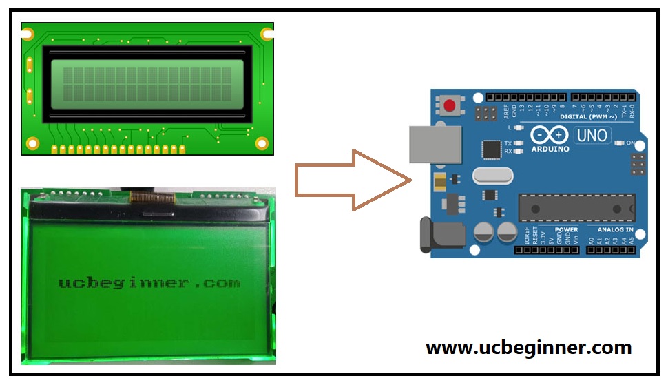
Since LCDs have a parallel interface, the microcontroller must manage several interface pins simultaneously to run the display. In this article, I’ll explain where and how to set up an LCD on an Arduino and then demonstrate several programming techniques. You’ll see how to print text, scroll text, make custom characters, make text blink, and position text. They are perfect for any project that produces data and may greatly enhance its interest and interactivity.

Interface-related PINs
The following pins make up the interface:
An RS pin for Register Selection
A data register, which retains the information shown on the screen, is an option. Consequently, the LCD’s controller has an instruction register that looks for instructions on what to do next. It chooses the location in the LCD’s memory where data is written.
Eight pins for data (D0 -D7)
These pins’ high or low states correspond to the bits transmitted to a register. Consequently, the values are read anytime you read or write.
A pin marked “read/write.”
You may choose between reading mode and writing mode.
Permit pin
You can write to the registers using it.
Additionally, there are connections for LED light (BKlt- and BKlt+), influence distribution pins (GND LED and +5V), and show contrast (Vo) for controlling the LCD, setting the show contrast, and turning on and off the LED backlight. Since the Liquid Crystal Library simplifies this, you don’t need to comprehend the low-level instructions. The data that creates the image of what you want to display must first be loaded into data registers to control the display.
For displaying text on a screen, you may use a 4-bit mode for nearly anything. Therefore this example shows how to use a 16×2 LCD in 4-bit format.
The 4-bit and 8-bit control modes are available on Hitachi-compatible LCDs. While the 8-bit mode requires eleven Arduino I/O pins, the 4-bit option only requires seven.
Hardware needed includes an LCD that works with the Hitachi HD44780 driver, an Arduino board, a 220-ohm resistor, hookup wires, and pin headers for the breadboard’s liquid crystal display pins.
How does Liquid Crystal Display function?
The process for sending data (to be shown) to an LCD is as follows. The LCD provides data to the data bus. The D4 and D7 pins (data bus) receive data from the Arduino. The RS pin is set to HIGH by the Arduino (to select the data register. The LCD keeps the collected data in the data resistor because the RS pin is HIGH. Then, using an LCD, the data is shown on the screen.
Commands for Liquid Crystal Display
A command’s transmission to an LCD’s process, for example, blinking the LCD, moving the pointer to a certain place, or clearing the display.
- The RS pin is set to LOW by the UNO.
- The D4 and D7 pins receive a command from Arduino (data bus).
- The LCD provides data to the data bus.
- The LCD keeps the data it receives in the command resistor since the RS pin is LOW. Afterward, the LCD responds by the value of the command.
Purchase Blue 1602 LCD 16×2 Character LCD Arduino from HALLROAD
Conclusion
A particular type of flat panel display known as an LCD (Liquid Crystal Display) operates primarily on liquid crystals. Since they are often used in cellphones, TVs, computers, and instrument panels, LEDs offer a wide range of applications for consumers and enterprises. Compared to a CRT, an LCD panel uses less energy and can be disposed of more securely. It may be utilized in battery-powered electronic devices more effectively than a CRT because of its minimal electrical power consumption.
