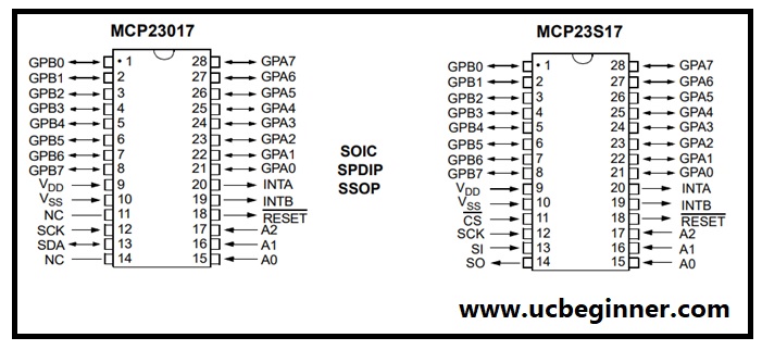
When working with microcontrollers like Arduino boards or other development kits, we often rely on GPIOs for input or output. Sometimes, our projects demand more GPIOs than the microcontroller can provide. For example, if we need 11 GPIOs but the microcontroller has only 6 available. In such cases, we can use a port expander IC to increase the number of GPIO pins. A popular choice is the MCP23017 / MCP23S17 ( MCP23X17 ), which offers 16 additional GPIOs that can be used for input or output to Arduino or other microcontrollers as well.
MCP23017/MCP23S17 (MCP23X17)
Unleash the power of your microcontroller or Arduino with the MCP23017/MCP23S17! This incredible 16-bit GPIO port expander IC is designed to seamlessly integrate with your setup, whether you use I2C or SPI serial using the interface.
For I2C enthusiasts, the MCP23017 is the best choice, while those opting for SPI can rely on the reliable MCP23S17. To know more about the key differences between MCP23017 and MCP23S17, be sure to visit our page on MCP23017 VS MCP23S17. Don’t miss out on expanding your possibilities!

These 16 GPIO are divided into 2 ports, PORTA and PORTB, MCP23x17 consists of 8-bit configuration registers, and the microcontroller can enable GPIO as either input or output by writing bits(IODIRA/B). MCP23X17 can operate in 8-bit or 16-bit mode via IOCON.BANK. It has 2 interrupt pins, INTA and INTB for PORTA and PORTB respectively. The Power-on Reset (POR) sets the registers to their default values and initializes the device state machine. Download the MCP23X17 datasheet for more information.
The MCP23X17 contains 22 individual registers (11 register pairs) that can be addressed through the Serial Interface block, as shown in the table below.
| Reflects the value of the port A | Address IOCON.BANK = 0 | Description |
| IODIRA | 0x00 | Controls the direction of the data I/O for port A |
| IODIRB | 0x01 | Controls the direction of the data I/O for port B |
| IPOLA | 0x02 | Configures the polarity on the corresponding GPIO_ port bits for port A |
| IPOLB | 0x03 | Configures the polarity on the corresponding GPIO_ port bits for port B |
| GPINTENA | 0x04 | Controls the interrupt-on-change for each pin of port A |
| GPINTENB | 0x05 | Controls the interrupt-on-change for each pin of port B |
| DEFVALA | 0x06 | Controls the default comparison value for interrupt-on-change for port A |
| DEFVALB | 0x07 | Controls the default comparison value for interrupt-on-change for port B |
| INTCONA | 0x08 | Controls how the associated pin value is compared for the interrupt-on-change for port A |
| INTCONB | 0x09 | Controls how the associated pin value is compared for the interrupt-on-change for port B |
| IOCON | 0x0A | Controls the device |
| IOCON | 0x0B | Controls the device |
| GPPUA | 0x0C | Controls the pull-up resistors for the port A |
| GPPUB | 0x0D | Controls the pull-up resistors for the port B pins |
| INTFA | 0x0E | Reflects the interrupt condition on the port A pins |
| INTFB | 0x0F | Reflects the interrupt condition on the port B pins |
| INTCAPA | 0x10 | Captures the port A value at the time the interrupt occurred |
| INTCAPB | 0x11 | Captures the port B value at the time the interrupt occurred |
| GPIOA | 0x12 | Reflects the value on port B |
| GPIOB | 0x13 | Reflects the value on the port B |
| OLATA | 0x14 | Provides access to the port A output latches |
| OLATB | 0x15 | Provides access to the port B output latches |
Operating Voltage:
- 1.8V to 5.5V @ -40°C to +85°C
- 2.7V to 5.5V @ -40°C to +85°C
- 4.5V to 5.5V @ -40°C to +125°C
Packages:
- 28-pin QFN, 6 x 6 mm Body
- 28-pin SOIC, Wide, 7.50 mm Body
- 28-pin SPDIP, 300 mil Body
- 28-pin SSOP, 5.30 mm Body
You can purchase from:
Mouser (MCP23017T-E/SS) and Digikey (MCP23S17-E/SP, MCP23S17T-E/SS)
How to use MCP23017/MCP23S17 (MCP23X17)
We can use it with Arduino using the Arduino library, and we can use it by configuring its register with SPI commands.
MCP23S17 with Arduino Library
Download the Arduino library for MCP23S17 and include this library in Arduino, In Arduino IDE click on Sketch >include library > Add .zip Library…
This library has 5 examples:
- MCP23S17_digitalRead
- MCP23S17_digitalWrite
- MCP23S17_performance
- MCP23S17_test
- MCP23S17_test_connection
MCP23017 with Register configuration
We will manually send the command through SPI to configure the registers of MCP23S17. Please see the code below to understand the working of MCP23S17 without the Arduino library.
Arduino Code for MCP23S17
MCP23S17_GPIO_WRITE Code
#include <SPI.h>

#define   CS_MCP 7

void setup() {
    pinMode(CS_MCP, OUTPUT);
    digitalWrite(CS_MCP,HIGH);

    SPI.begin();

    digitalWrite(CS_MCP, LOW);
    SPI.transfer(0x40);
    SPI.transfer(0x01);
    SPI.transfer(0x00);
    digitalWrite(CS_MCP, HIGH);
  }

void loop() {

    digitalWrite(CS_MCP, LOW);
    SPI.transfer(0x40);
    SPI.transfer(0x13);
    SPI.transfer(0x01);
    digitalWrite(CS_MCP, HIGH);
    delay(500);

    digitalWrite(CS_MCP, LOW);
    SPI.transfer(0x40);
    SPI.transfer(0x13);
    SPI.transfer(0x00);
    digitalWrite(CS_MCP, HIGH);
    delay(500);
   }
Code Explanation

pinMode(CS_MCP, OUTPUT);
digitalWrite(CS_MCP,HIGH);

SPI.begin();

digitalWrite(CS_MCP, LOW);
SPI.transfer(0x40);
SPI.transfer(0x01);
SPI.transfer(0x00);
digitalWrite(CS_MCP, HIGH);
In Void Setup() first set the direction of CS_MCP as output, initialize the SPI then initialize the MCP23S17 to write on GPIO.
    digitalWrite(CS_MCP, LOW);
    SPI.transfer(0x40);
    SPI.transfer(0x13);
    SPI.transfer(0x01);
    digitalWrite(CS_MCP, HIGH);
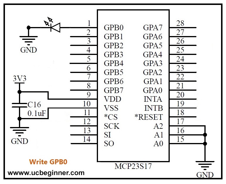
In void loop() we clear the CS_MCP, send SPI command (SPI.transfer(0x40);) to set MCP23S17 to write on GPIO, send SPI command (SPI.transfer(0x13);) select Port B, then send the SPI command (SPI.transfer(0x01);) to set the pin no. 1 of port B, thus the LED attaches to pin no. will be on, see figure no. 2.
MCP23S17_GPIO_READ Code
#include <SPI.h>

#define CS_MCP 7
unsigned char  MCP_state = 0;

void setup() {
    pinMode(CS_MCP, OUTPUT);
    digitalWrite(CS_MCP,HIGH);
    pinMode(LED_BUILTIN,OUTPUT);
    SPI.begin();

    digitalWrite(CS_MCP, LOW);
    SPI.transfer(0x41);
    SPI.transfer(0x12);
    MCP_state = SPI.transfer(0x12);
    digitalWrite(CS_MCP, HIGH);
  }


void loop() {
    digitalWrite(CS_MCP, LOW);
    SPI.transfer(0x41);
    SPI.transfer(0x12);
    MCP_state = SPI.transfer(0x12);
    digitalWrite(CS_MCP, HIGH);

    if(MCP_state == 0x7F)
      { digitalWrite(LED_BUILTIN, HIGH); }

    if(MCP_state == 0xEF)
      { digitalWrite(LED_BUILTIN, LOW);  }
   }
Code Explanation

    pinMode(CS_MCP, OUTPUT);
    digitalWrite(CS_MCP,HIGH);
    pinMode(LED_BUILTIN,OUTPUT);
    SPI.begin();

    digitalWrite(CS_MCP, LOW);
    SPI.transfer(0x41);
    SPI.transfer(0x12);
    MCP_state = SPI.transfer(0x12);
    digitalWrite(CS_MCP, HIGH);
In void setup() set the direction of CS_MCP, initialize the SPI then initialize the MCP23S17.
    digitalWrite(CS_MCP, LOW);
    SPI.transfer(0x41);
    SPI.transfer(0x12);
    MCP_state = SPI.transfer(0x12);
    digitalWrite(CS_MCP, HIGH);

    if(MCP_state == 0x7F)
      { digitalWrite(LED_BUILTIN, HIGH); }

    if(MCP_state == 0xEF)
      { digitalWrite(LED_BUILTIN, LOW);  }
In void loop() we send the SPI command (SPI.transfer(0x41);) to read the pins of MCP23S17, send the SPI command (SPI.transfer(0x12);) to select Port A then read the Port A (MCP_state = SPI.transfer(0x12);).
    if(MCP_state == 0x7F)
      { digitalWrite(LED_BUILTIN, HIGH); }

    if(MCP_state == 0xEF)
      { digitalWrite(LED_BUILTIN, LOW);  }
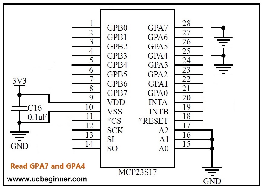
In this code we continuously read port B and when we connect the ground to PIN no. 28 MCP23S17 sends 0x7F then the builtin LED will on, and when we connect the ground to PIN no. 25 then MCP23S17 sends the 0xEF, and Builtin LED will be off, see the Figure no. 3.
In a nutshell
Fear not when your microcontroller’s GPIOs run low! Here comes the MCP23S17 to save the day. By harnessing the power of this wonder chip, you can easily increase your GPIO count and configure it for both input and output. Just correct the MCP23S17’s register settings using the SPI protocol, and you’re good to go. Say goodbye to GPIO limitations and hello to endless possibilities!

good effort